



How to Select a Neutral Grounding Resistor for a Medium-Voltage Power System
Introduction
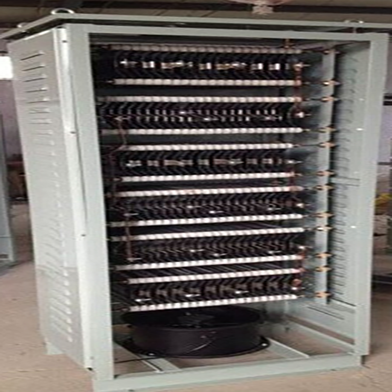
A neutral grounding resistor (NGR), also called a neutral earthing resistor, connects the neutral point of a transformer or generator to ground through a defined resistance. Its purpose is not simply to “add resistance.” A correctly selected NGR limits ground-fault current to a controlled value, reduces equipment damage and arc-flash energy, and gives the protection system a measurable current for reliable fault detection.
Because every network is different, an NGR should be selected from electrical and environmental data rather than from voltage alone. The following factors form a practical starting point for utility, industrial, mining, oil and gas, and renewable-energy projects.
1. Confirm the system voltage and neutral voltage
Begin with the system line-to-line voltage and calculate the line-to-neutral voltage. For a three-phase system, the neutral-to-ground voltage during a single-line-to-ground fault is normally based on line-to-line voltage divided by the square root of three. The NGR insulation level, bushings, clearances and enclosure arrangement must be suitable for this duty and for the applicable project standard.
2. Define the target ground-fault current
The target current depends on the grounding philosophy and the protection scheme. High-resistance grounding commonly limits current to a low value so that equipment damage is minimized and, where the operating philosophy allows, the system may continue operating briefly after the first fault. Low-resistance grounding permits a higher current so protective relays can detect and clear the fault quickly.
The selected current must be high enough for dependable relay operation but low enough to protect the generator, transformer, cables, switchgear and connected loads. A system study should confirm the final value.
3. Calculate the required resistance
The basic relationship is R = V/I, where V is the neutral-to-ground voltage during the fault and I is the desired ground-fault current. This calculation establishes the nominal resistance at the specified reference temperature. The design must also consider resistance tolerance and the change in resistance as the elements heat during a fault.
4. Select the fault duration and thermal rating
NGRs are commonly specified for short-time duty or continuous duty. A short-time rating may be 10 seconds, 30 seconds, 60 seconds or another project-defined duration. Continuous-duty designs are required when the grounding philosophy permits prolonged operation with a ground fault. The resistor grid material, element mass, ventilation and enclosure must safely absorb the resulting energy without exceeding the permitted temperature rise.
5. Check the installation environment
Indoor or outdoor location, ambient temperature, altitude, humidity, pollution, salt, dust, seismic conditions and available space can all change the mechanical and insulation design. Outdoor NGR cabinets should have an enclosure protection level and corrosion system suited to the site. Space heaters, anti-condensation controls, current transformers, monitoring relays and disconnecting devices can be incorporated when required.
Information to include in an NGR inquiry
For an accurate quotation, provide the system voltage and frequency, transformer or generator neutral rating, required fault current, fault duration, insulation level, indoor or outdoor location, ambient conditions, enclosure requirement, applicable standard, accessory list and preferred cable-entry direction. A single-line diagram and protection philosophy are especially useful.
Baoding Weifan Electrical Technology Co., Ltd. supplies neutral grounding resistors and related neutral earthing equipment for project-specific power systems. Contact the Electric Valley team with your system data for technical review and a tailored proposal.
 How to Select a Neutral Ground
 AIS vs. GIS vs. Solid-Insulate
 Distribution Transformer Buyin
 How Current-Limiting Reactors